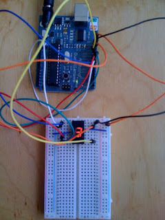
Drawing an Arduino Circuit Diagram

I've had an Arduino Duemilanove now for a couple of weeks. If you're not familiar with the Arduino, it is "an open-source electronics prototyping platform based on flexible, easy-to-use hardware and software". It has a small microcontroller, a USB port to connect to your computer for programming, a power socket for providing power when the USB cable isn't connected, and various digital and analog input and output pins, for connecting up to leds, switches and various sensors.
It's inexpensive, and there's an open source IDE for programming. Works great, but one issue that I quickly ran into was remembering my circuits. I'd make something up on a breadboard, write a program for it, and then tear it apart to build another circuit. When I wanted to go back to an earlier circuit, I had the program saved, but I couldn't always remember how I had wired up the circuit.
So I went looking for a program that would let me document my circuits, and I found Fritzing. It's very easy to use. You drag parts off a palette and connect them up with drag and drop. You can work on a breadboard view or a schematic view, and they are automatically kept in sync. You can easily put bends into wires to route them in more visually appealing ways.


Here's an example of a circuit using the Arduino Duemilanove and a 7 Segment Red LED 0.3" Digital Display (RadioShack 276-075).
Building this I was able to experiment with another feature of Fritzing, because the 7 Segment LED included in the core parts of the tool was a common anode numerical display. Although these pictures don't show anode/cathode on the pins, it is visible in the tool, and I wanted to get it right. So I edited the part, changed the pin wiring, and saved it as a new part. This was all very straightforward.
Then I decided I wanted to have the pins be labeled A, B, C so that it would show up in the schematic view. All the images are SVG, and I didn't have an SVG editor handy, so I used svg-edit, an online browser based editor. I copied the "7-segment display.svg", added the letters, saved it into a new svg file, and selected it within fritzing. I did need to close and reopen Fritzing for it to refresh the schematic which already had the old image on it, but I didn't need to remove and re-add.
I'm still experimenting with Fritzing, but for something that I've only been using for an hour or so I've found it remarkably full featured and easy to use. It would be nice if it had a "snap to grid" feature that would recognize when I'm trying to route my wires horizontally and vertically and fix things when I'm just a little off. But that's really just a nit - and maybe something it has and I just haven't found yet.
One more thing that Fritzing can do is create a PCB layout in various formats, that can be used to manufacture the circuit boards. For example, you can export as a Gerber file and use a printed circuit board fabrication service like BatchPCB.
Lastly, in case you were looking for how to count from 0 to 9 on the above circuit over and over again, here's the sketch
// Counting on a 7-Segment Red LED (common cathode) numerical display
// RadioShack 276-075 / Wiring
//
//  arduino pin -> 7-segment LED pin -> anode
//  13 -> 14 -> A      --A--
//  12 -> 13 -> B     |     |
//  11 ->  9 -> RHDP  F     B
//  10 ->  8 -> C     |     |
//   9 ->  7 -> D      --G--
//   8 ->  6 -> E     |     |
//   7 ->  2 -> G     E     C
//   6 ->  1 -> F     |     |
//                     --D-- O

int ledPins[]={0xDD,0x50,0xCE,0xDA,0x53,0x9B,0x9F,0xD0,0xDF,0xD3};

void setup()
{
  for (int i=6;i<14;i++) {
    pinMode(i,OUTPUT);
  }
}

void loop()
{
  for (int i=0; i<10; i++) {
    displayNumber(i);
    delay(500);
  }
}

void displayNumber(int num)
{
  for (int i=0; i<8; i++) {
    digitalWrite(i+6, bitRead(ledPins[num],i));
  }
}